Welcome to Part 2 of my series on writing a raytracer in Rust. If you haven’t already, you may wish to read Part 1. Previously, we implemented a basic raytracer which can render only a single sphere with no lighting. This time, we’ll add multiple objects, planes, and basic lighting.
Multiple Objects
It’s pretty easy to change our scene definition to contain a Vec of spheres instead of just a single one. Once we have multiple spheres, however, we need to know which one our ray hit. This is easy if they don’t overlap on the screen. If they do, we can find the correct sphere by taking the nearest intersection to our camera. That means we need to know the distance to the intersection, not just whether there is an intersection or not.
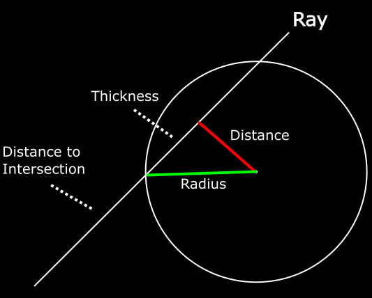
This requires a bit more geometry. Recall from last time that we detect an intersection by constructing a right triangle between the camera origin and the center of the sphere. We can calculate the distance between the center of the sphere and the camera, and the distance between the camera and the right angle of our triangle. From there, we can use Pythagoras’ Theorem to calculate the length of the opposite side of the triangle. If the length is greater than the radius of the sphere, there is no intersection.
There are more right triangles formed by the ray than just this one, however. If we instead create a triangle between the point that the ray intersects the sphere and the center of the sphere, we can again use Pythagoras’ Theorem to calculate the distance from our right angle to the intersection point. Subtracting that from the distance from the camera to the right angle gives the distance to the intersection point.
To put that in code, here are the changes to our Sphere intersection method:
Now that we know the distance to the intersection, we need a method to perform the iteration and return the nearest intersection. It’s also useful to return a reference to the object itself (for example, so we can use the right color). Notice that we have to use partial_cmp and unwrap to compare the distances. This is an instance where Rust’s strict type safety sort of gets in the way - because some values (NaN, +-Infinity) can’t be correctly compared, f64 doesn’t implement the Cmp trait. In this case, no valid intersection can ever contain those values so we should be safe just using unwrap. It’s a bit ugly, but it’s probably better than tracking down strange bugs related to NaN-safety later.
Planes
Next up we’ll add Planes as an object to test our rays against. There are a few ways to represent planes in 3D space, but for our purposes the most convenient is to define a point on the plane, and the normal of the surface. Before we implement the intersection test though, we need to adapt our scene structure so it can contain an arbitrary number of spheres or planes.
We could try adding another Vec of Plane structures, but that gets annoying quickly. We’d have to duplicate some logic (eg. the trace method) to apply to both the spheres and the planes. Some sort of dynamic dispatch is appropriate here. Rust provides two ways to do this. We could either wrap each object in a variant of an Enum or we could use Trait Objects. I’ve chosen to go with the former, but it’s mostly a matter of personal preference.
Now that we have our Plane structure, how can we test for an intersection? One convenient property of planes is that they’re infinitely large. If a plane isn’t perfectly parallel to our ray, it will always intersect eventually. We can test this with the dot product - if the dot product between the ray and the normal of the plane is zero (give or take a bit to account for floating-point error) then it’s parallel and thus there is no intersection. Otherwise, there is an intersection somewhere.
However, we need to know where that intersection is. I’m afraid that I haven’t been able to find a good intuitive or geometric explanation of why this works, so I’ll just have to direct you to Scratchapixel, where they show the full derivation of the equation.
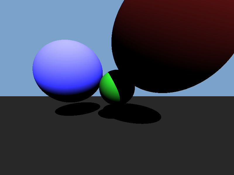
Now that all of that’s done, let’s take a moment to admire our handywork.
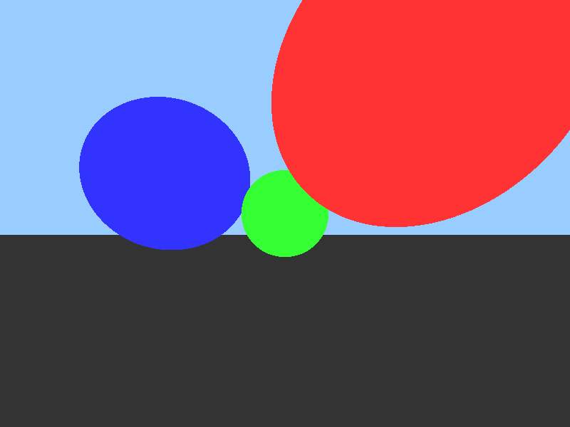
Yeah, I know. Five minutes in MS Paint, amirite? It will look better once we start adding lighting effects.
Directional Lights
We’ll start by adding a single directional light to our scene. Directional lights approximate light from the sun or stars - objects so far away that their light rays are effectively parallel to each other and at an approximately-constant intensity level. As a result, they’re also simpler than closer point-source lights.
Next we need to know the surface normal of the object at the point our ray intersected with it.
Sphere:
fn surface_normal(&self, hit_point: &Point) -> Vector3 {
    (*hit_point - self.center).normalize()
}
Plane:
fn surface_normal(&self, _: &Point) -> Vector3 {
    -self.normal
}
Finally, we’ll need to add an albedo to our Spheres and Planes. This is simply a parameter which specifies how much light energy is reflected by an object and how much is absorbed.
Now to actually implement the shading. First some preparation.
let intersection = scene.trace(&ray);
let hit_point = ray.origin + (ray.direction * intersection.distance)
let surface_normal = intersection.element.surface_normal(&hit_point)
let direction_to_light = -scene.light.direction
Now we calculate the amount of light that lands on this point. This is proportional to the cosine of the angle between the surface normal and the direction to the light (Lambert’s Cosine Law). The dot product is the length of one vector times the cosine of the angle between them, but because we use normalized vectors the length will be one. We also add a factor for the brightness of the light.
let light_power = (surface_normal.dot(&direction_to_light) as f32) *
    scene.light.intensity;
Then we calculate the proportion of the light which is reflected. This is equal to the albedo of the object divided by Pi. Once again I have to admit that I can’t find a good explanation of this formula. If you’re really interested, you can once again check out Scratchapixel’s derivation (be warned - this one contains integrals). The short version is that dividing by Pi ensures that the object doesn’t reflect away more energy than it receives.
let light_reflected = intersection.element.albedo() / std::f32::consts::PI;
Finally we accumulate this together into the final color for the pixel. We represent colors as (R, G, B) triplets where each value is in the range 0.0…1.0. We can multiply colors by multiplying each value - eg. if the red component of a light is 0.5 and the object reflects 0.5 of red light, the viewer will receive a red value of 0.25.
let color = intersection.element.color() * scene.light.color *
            light_power * light_reflected;
Or, all together:
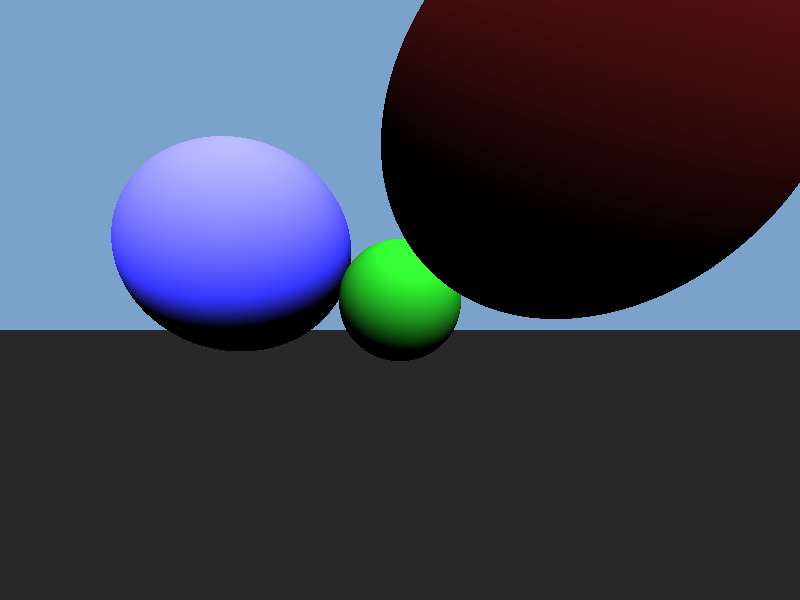
It’s still not quite right though - none of the spheres are casting shadows, on the lower plane or on each other.
Shadows
Calculating shadows in a raytracer is really easy. Simply trace another ray from the intersection of the prime ray and the object back to the light. If there is another object between the intersection and the light, the point is in shadow.
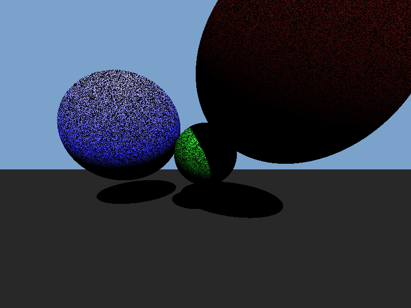
Well, that’s not quite right. We have shadows on the lower plane and the green sphere, but also a lot of noise. The dark noise is called ‘shadow acne’ and it occurs because our floating point values have limited precision. Sometimes, the hit point will be ever so slightly inside the intersected object and so the shadow ray will intersect with the same object the prime ray did. It might seem like we could simply ignore that object when tracing the shadow ray, and for this simple geometry we could. If we had more complex objects though (eg. a model of a tree) we would want an object to be able to cast shadows on itself, so that won’t work. Instead, we simply add a tiny fudge factor and adjust the origin of the shadow ray a short distance along the surface normal so that we can be sure it’s outside the object. It doesn’t have to be much - I’ve found that bias values as small as 1e-13 were enough to eliminate visible shadow acne.
let shadow_ray = Ray {
    origin: hit_point + (surface_normal * scene.shadow_bias),
    direction: direction_to_light,
};
Multiple Lights
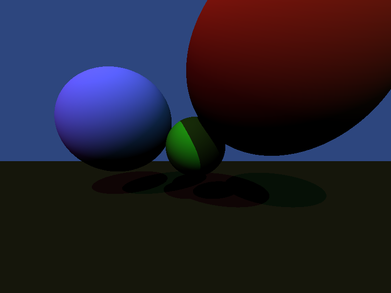
It’s pretty easy to implement multiple lights as well. The light the camera sees from any particular point is equal to the sum of the contributions from each individual light source. We can just iterate through the lights, accumulating together the color values from each.
This produces the following image - notice the two sets of shadows.
Spherical Lights
Finally, we’ll add Spherical Lights (or point lights). First some definitions. Again, I’m using an enum for dynamic dispatch.
Next up, we need to know the direction to the light. This is easily calculated:
(s.position - *hit_point).normalize()
The intensity of these lights obeys the Inverse Square Law, so we calculate the intensity by dividing the light’s intensity value by 4*Pi*distance^2. Incidentally, this means that the intensity values of spherical lights in your scene definition must be much larger than for directional lights.
let r2 = (s.position - *hit_point).norm() as f32;
s.intensity / (4.0 * ::std::f32::consts::PI * r2)
Additionally, our shadow test needs to be changed a bit. For directional lights, we only had to check if there was any intersection in the direction of the light. That won’t work now - what if there’s an object on the far side of the light? Instead we check if the nearest intersection is closer than the light itself is.
let shadow_intersection = scene.trace(&shadow_ray);
let in_light = shadow_intersection.is_none() ||
    shadow_intersection.unwrap().distance > light.distance(&hit_point);
Putting that all together produces this:
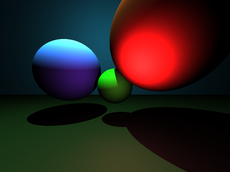
Try doing that in five minutes in MS Paint!
Conclusion
We’ve taken this toy raytracer from producing an image of a green circle to a nicely-lit scene containing multiple objects. The last entry in this series will go on to add texturing as well as simple reflection and refraction simulations. As before, if you want to try playing around with the code yourself, you can check out the GitHub Repository.